-
Hotline0086-755-27198826-601
- emai:y@3nh.com
- add:F/6, Block 5B, Skyworth Inno Valley, Tangtou 1st Road, Shiyan, Baoan District, Shenzhen, P.R. China.
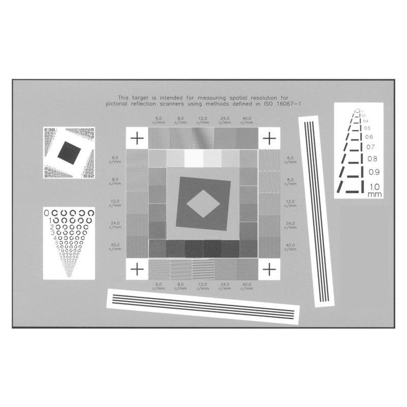

SINEIMAGE ISO-16067 Reflection Scanner Test Chart QA-61
- Product Instroduction The above image is an approximate representation of the actual product. Specifications are subject to change without notice. Desc
ription: Test array meeting the specified requirements of ISO-16067-1. Substrate Size: 10

-
Product details
-
Parameters
Product Instroduction
The above image is an approximate representation of the actual product.
Specifications are subject to change without notice.
Description: Test array meeting the specified requirements of ISO-16067-1.
Substrate Size: 100mm x 152mm
Substrate Type: White reflective photo paper
Image Forming Material: Photographic emulsion
Image Description: Includes slant edge, alphanumeric resolution chart, Landolt Ring chart, gray step patches. Horizontal, vertical and slanted Ronchi patterns are provided at 6 to 40c/mm. Applied Image has also provided (as permitted in section 4.1.2 of the standard) a T-100 Digital Electronic Pixel Target that has horizontal, vertical and slanted bars in widths from 0.1 to 1.0mm (width to length ratio is 1:5).
Polarity: Positive and primarily gray.
Reading Direction: Right Read Emulsion Up (RREU).
Image Placement Accuracy: Not applicable
Feature Size Accuracy: Typical line width is 2 to 5 percent of aim.
Image Contrast / Density: As specified in ISO-16067-1.
History / typical use: To determine reflective light resolution and imaging characteristics of recording devices.
Other: A Windows executable program (2.5 MB zip file) is available for download from www.i3a.org. That executable is a target format (ISO 16067-1) specific version of sfrwin that allows the user to easily select fiducial mark locations through a GUI. Four SFR estimates (two horizontal and two vertical) are generated based on pre-defined edge locations as well as Opto-Electronic Conversion Function (OECF) and noise data for target gray patches. TIFF and BMP files are the acceptable input formats.
Related Parts: QA-62, QA-76, QA-72, QA-77
Target Information
The ISO-16067-1 target is made on a black & white silver halide reflective media. It is spectrally neutral, of high spatial frequency content and conforms to the target specifications outline in ISO 16067-1, Electronic scanners for photographic images – Spatial resolution Measurements – Part1:
scanners for reflective media.
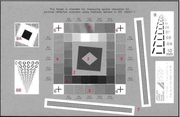
1.Neutral tone scale patches
Used to measure a device’s Opto-Electronic Conversion Function (OECF). The OECF is the relationship between physical optical density and scanner count value. The nominal reflection densities for each patch are indicated on the reverse side. The user is encouraged to verify or supersede these with their own densitometry.
2.Near-vertical and near-horizontal slanted edges
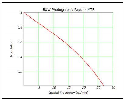
With the aid of appropriate software, these features are used to measure the vertical and horizontal spatial frequency response (SFR) or Modulation Transfer Function (MTF) of a device. They are rotated approximately 5 degrees from horizontal and vertical directions and have approximately a 60% contrast modulation. This relatively
low contrast ratio is designed to minimize MTF estimation errors. The following equation indicates a typical MTF response (ISO-16067-1 Section 4.2.5).
where ν equals spatial frequency in cycles/mm and is less than or equal to 80 cycles per mm. For rigorous MTF estimates this target response needs to be considered, especially at resolutions greater than 1200 dpi.
3.Near 45° edges
These features are used to aid in measuring the MTF at 45° diagonal.
4.Vertical and horizontal square wave features.
These test features are intended to aid in the visual detection of aliasing. These features have a spatial frequency of 6, 8, 12, 24, and 40 cycles/mm and roughly correspond to sampling frequencies of 300, 400, 600, 1200, and 2000 dpi respectively.
5.Near-vertical and near-horizontal square wave features
These test features are similar to #4 but because of their slant will tend to reduce the visual impression of phase-induced aliasing.
6.Fiducial or Registration marks
As indicators of position and distance, these marks may be useful in automated analysis and sampling verification of a scanner. Nominally, the vertical and horizontal distances between each mark is 50.8 mm.
7.Slightly Slanted Extended Lines – high contrast
Helpful in verifying scan linearity, “stair stepping”, cyclical scan artifacts, and color miss-registration.
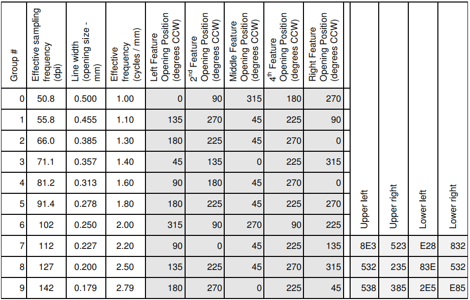
8.Bitonal spatial resolution elements
Intended to correlate traditional limiting visual resolution with MTF results. A R.I.T. Alphanumeric target is located in the upper left. A Landolt “C” test pattern is located in the lower left. The numbered groups correspond to patterns of know spatial frequencies. The group number for both targets and corresponding spatial frequencies are listed below along with size, resolution and orientation.
10.T-100 Digital Electronic Pixel Target
This area contains horizontal, vertical and slanted bars (1:5 Ratio) in widths from 0.1 mm to 1.0 mm.
Nominal Patch Reflection Densities (starting at upper right and proceeding clockwise)