


-
Hotline0086-755-27198826-601
- emai:y@3nh.com
- add:F/6, Block 5B, Skyworth Inno Valley, Tangtou 1st Road, Shiyan, Baoan District, Shenzhen, P.R. China.
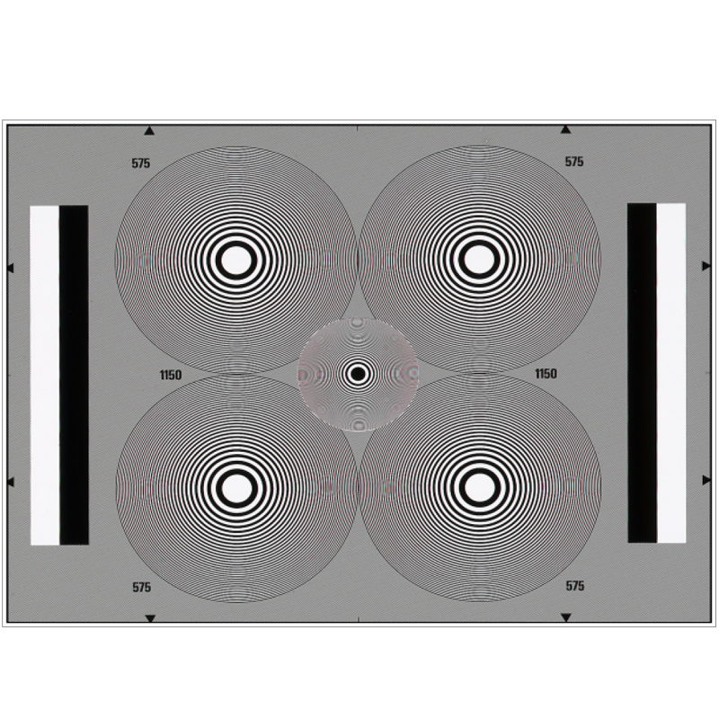

Zone Plate Test Chart Y063
- Product Introduction Checking resolution characteristics and cross color interferences of TV cameras and TV transmission systems D ATA On a neutral surrounding area with a density of D ~ 0.4 four large zone plates are arranged. Each zone pl

-
Product details
-
Parameters
Product Introduction
Checking resolution characteristics and cross color interferences of TV cameras and TV transmission systems
DATA
On a neutral surrounding area with a density of D ~ 0.4 four large zone plates are arranged. Each zone plate consists of concentric circular rings, with their width and distances decreasing outwards. The geometry of the circular rings causes the space frequencies of the zone plate to increase linearly with the distance from the circle center. At the outer edge of the circular rings we have 575 lines per picture height and thus a spatial frequency of 575/2 = 287.5 periods or line pairs per picture height. In our 625 line TV system (575 active lines, 52 µs active line duration, aspect ratio 4:3) this corresponds to a frequency of 7.4 MHz in horizontal direction. According to the scanning theorem horizontal lines of 287.5 periods per picture height can just or just not be resolved (Nyquist frequency) by a 625 line TV system.
In the picture center there is a small zone plate with the spatial frequencies being twice as high as those of the large zone plates. At the outer edge of this central circular field we have a spatial frequency of 1150/2=575 periods or line pairs per picture height. This corresponds to a frequency of 14.8 MHz in horizontal direction.
The left and right edges of the picture show one white and one black vertical bar each with densities of D~0.1 resp. D~1.7. These bars serve as a reference when measuring the resolution by oscilloscope as well as for level adjustment.
UTILISATION
The Zone Plate method has proved worthwhile especially for subjective comparison measurement at the TV screen. For objective measurement it is less suitable. Therefore it is not an in service test method. The Zone Plate method is rather an important aid for developing new systems and devices. And it also can be recommended for comparison during approval measurements.
With the aid of the Zone Plate method the following characteristics of TV cameras can be determined:
• resolution in horizontal, vertical and diagonal direction
• correlation between the resolution and the scanning spot
• effects of horizontal and vertical aperture corrections
• astigmatism of the camera scanning beam (tube cameras)
• effects of interferences between the zone plates and the television line resp. the shadow mask structure of color picture tubes
• effects of PAL coding (e.g. cross color)
• reaction during horizontal and vertical movement of the camera (or the test chart)
• dynamic resolution
• temporal interferences (e.g. due to cross color)
The use of the Zone Plate method is particularly recommended for test objects where the television signal is filtered multidimensonally (horizontally, vertically and temporally). These can be aperture correctors of TV cameras or standard PAL-decoders (with line delays) and combifilter PAL-decoders. Zone Plates also allow to determine the effects of pre- and post-filtering of MAC-systems (with line-sequential color transmission). Particularly useful is the optical Zone Plate Test Chart for checking CCD cameras.
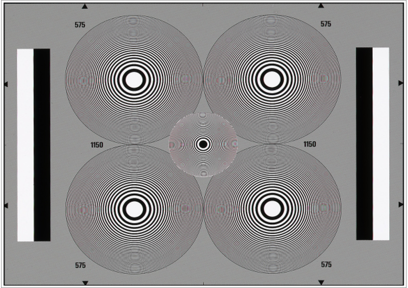
When measuring resolution it has to be noted that with the optical Zone Plate Test Chart the density in the circular fields changes rapidly. This means that besides the fundamental wave of the space frequencies there are also harmonic waves. When scanning the zone plates with the TV line system those harmonic waves which surpass the Nyquist frequency may cause interference patterns in the television picture (the so-called aliasing components) which again show zone plates. These interference zone plates result from interference between the Zone Plates of the test chart and the scanning television line system. Due to the interlaced scanning the interference zone plates are not static but flicker in a 25 Hz rhythm.
When working with cameras with electron-optical scanning (tube cameras) these interferences are usually very low since the scanning electron beam has a distinct low-pass filter characteristic due to its three-dimensional extension. This leads to a pre-filtering of picture shot. The reaction with CCD cameras is different. Due to the clearly defined geometric structure of the CCD elements in horizontal and vertical direction noticeable interference patterns both horizontally and vertically may occur (see picture).
During PAL-transmission ther are in addition cross-color interferences through cross-talking of light density components in the chromatic chain. During reproduction of a PAL-coded Zone Plate Test Chart on a color monitor the cross-color interferences can be seen as small pulsating colored zone plates with their centers lying in horizontal direction at the PAL color sub-carrier frequency 4.43 MHz. When the PAL decoder works with comb filters the cross-color interferences are generally less significant in stationary pictures than in moving pictures (i.e. when camera or test chart is moved).
In fact the PAL coder and especially the PAL decoder are primarily responsible for the cross color interferences, but even a too “sharp” aperture correction may increase the cross color considerably. In order to locate the cause of cross color interferences it is recommended to work not only with the optical Zone Plate Test Chart (and the camera) but also with an electronic zone plate generator.
In general it is recommended to use a zone plate generator whenever test object has electric inputs. These are besides transmission devices like a aperture correctors, PAL coders and decoders also monitors. Compared to the optical Zone Plate Test Chart zone plate generators have the advantage that the output signals of the zone plate can either be generated in a square shape or as continuous sinusoidal transitions. Dynamising the Zone Plate can also be effected easily in an electronic way.